This article is Part III of a series called Track Your Adventures for Free where I outline how to use Ham Radio and your Smartphone as an affordable APRS tracking system. For reference, here are links to the first 2 parts:
In part II I closed on the mention of modifying the BaoFeng headset and a smartphone headset such that the speaker output of the BaoFeng radio is connected to the microphone input of the Smartphone, and also have the Smartphone speaker output connect to the BaoFeng radio’s microphone input. This is, for the most part, simple, but at Integrated Overland we like to build things that are technically sound and designed to remain functional. Yes, you could simply cut the wires off the ends of the cables and connect the Speaker + and – to the microphone + and -, but this will result in problems down the road that have the potential to damage either your radio or smartphone, or both. I am going to explain the technical details behind this, but I want to start off by ensuring you that doing it right is still a simple process and only requires adding 4 resistors. Don’t be discouraged by the tech talk, this is still very simple, and you can feel free to skip ahead if you just want to implement the solution. You can also skip the solution altogether and just pair the wires together, at the very end of the article I will discuss how to do this in a way that will minimize the risk, but given how simple the solution is, you may want to give it a shot.
So what’s the problem? The problem is that for both the radio and Smartphone, the speaker signals are designed to drive earphone speakers and produce audible noise. This means that the speaker outputs are higher power outputs. However, the microphone input for both and for most devices in general is designed to operate with low power signals that are generated by the microphone. This means that you are trying to put higher power signals from the speaker into a port that is designed for lower power signals. The speaker output levels for typical devices can range anywhere from 2V to 20V in amplitude (partially depending on the volume level). A microphone input level is typically on the lowest end of this spectrum at around 0.2V to up to around 2V. On an even more technical side note, the speaker and microphone ports have different impedance levels, but this is less important as we aren’t trying to achieve maximum signal transfer in either case.
So our basic problem is simple, we have a voltage level problem, we need to reduce the voltage, which is much easier than needing to amplify the voltage. We have to shift a 2V-20V signal into a 0.2V-2V signal. Incidentally, this is a 10 to 1 reduction, and because we all love technical details, we’ll mention this is a 20dB reduction.
The basic solution to a basic problem then becomes a basic voltage divider circuit (and the cessation of usage of the word basic). We need a 10:1 voltage divider, which can be achieved with 2 resistors. The resistors have to have a 10 to 1 difference to meet the criteria, so you can use a 1kΩ resistor, and a 100Ω resistor, or different combinations of 10 to 1 ratio values. However, I recommend that you use a 10kΩ resistor and a 1kΩ resistor. Why? Because this would put roughly a 10kΩ impedance on the speaker side (high side), and a 1kΩ impedance on the microphone side. This is more suitable for the application. Now, to properly cover the basics, below are 2 images of what this voltage divider circuit looks like.
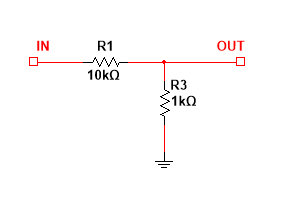
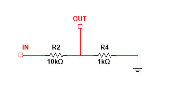
These two circuits above are exactly the same. I simply wanted to illustrate that the way these are shown in the schematic is not relevant to its operation in case we have readers who are unfamiliar with schematics. What matters is the order, meaning that the input side has to enter into the higher value 10kΩ resistor, and then at the other side of the 10kΩ resistor, you tap your output, but this same point is connected to ground via the 1kΩ resistor. How you lay it out in application does not matter as long as the connections are made at the correct point.
So we have solved the problem of reducing our signal levels, now how do we apply the solution to our particular problem? The answer is as follows:
Continue reading Track Your Adventures for Free – Part III – Making the Connection →

